Technical Library · Replacement-005
Transformer Replacement Outage and Commissioning Plan: Temporary Power, Testing and Energization
Engineering reference prepared by TransformerGrid · Project-specific requirements require manufacturer, utility and qualified-engineer verification.
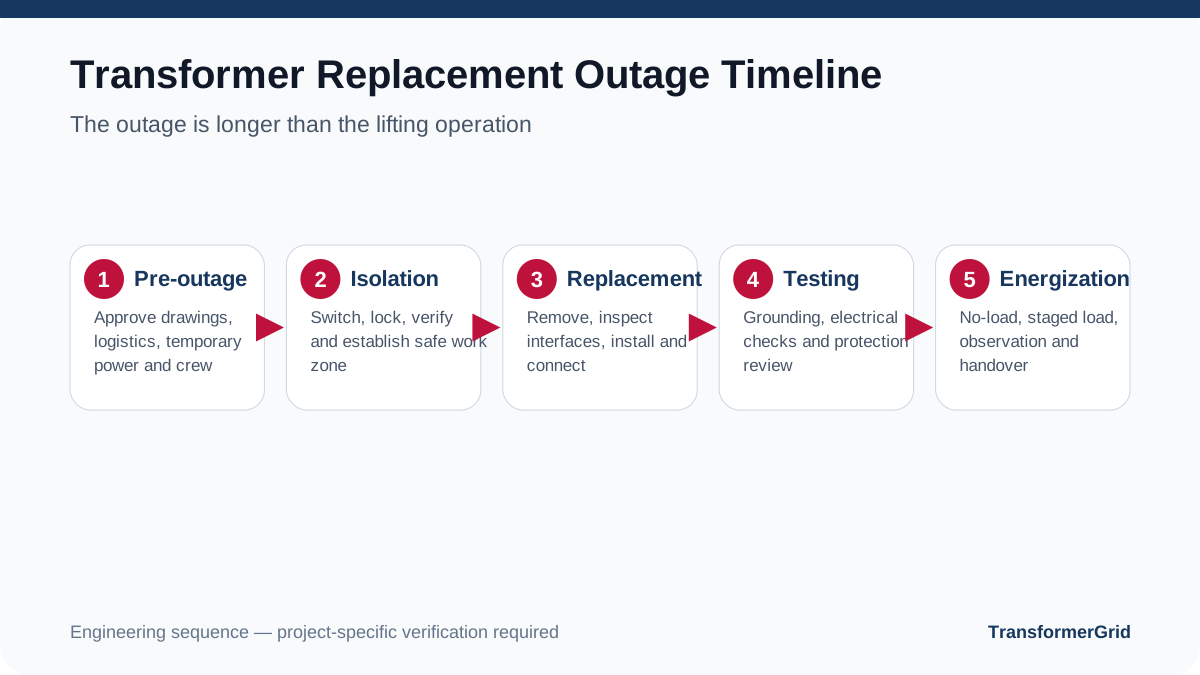
The Outage Window Starts with Load Criticality
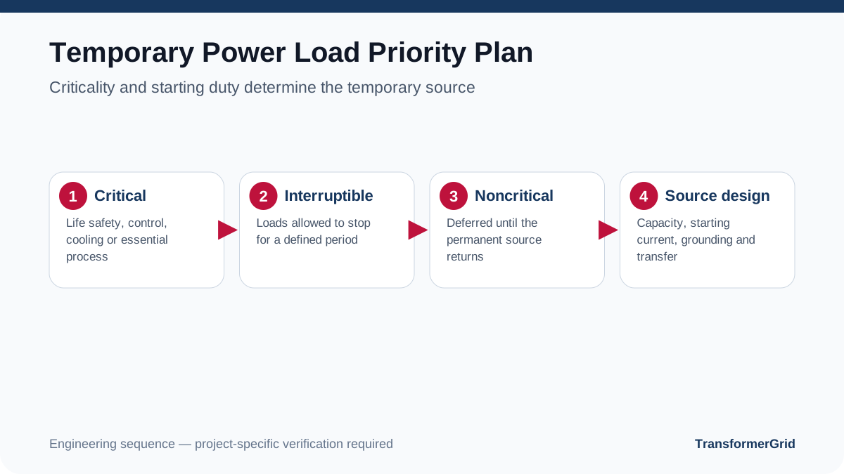
Replacement planning begins by identifying loads that cannot be interrupted, loads that can tolerate a defined outage and loads that can remain off. Hospitals, data systems, cold storage, pumps, production lines and communications have very different consequences of loss of supply.
The outage duration is not the crane time. It includes isolation, verification, removal, interface inspection and repair, installation, connection, testing, protection confirmation, energization and observation.
Temporary-Power Strategy
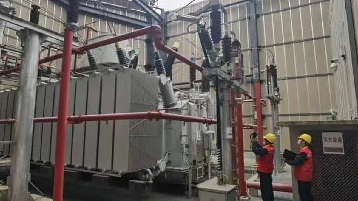
Options may include generators, a temporary transformer, load transfer, sectionalized supply or planned production shutdown. Confirm capacity, starting current, power factor, grounding, neutral arrangement, transfer method, fuel, emissions, fire safety, operating personnel and required runtime.
Temporary power is a designed electrical system, not an informal cable connection. It must be engineered and operated by qualified personnel under local safety and interconnection requirements.
Pre-Outage Readiness and Go/No-Go Conditions
Equipment, accessories, approved drawings, test documents, lifting plans, vehicles, tools and personnel should be confirmed before isolation. Pole, foundation, cable, grounding and clearance problems should be exposed in advance where reasonably possible.
Examples of no-go conditions include missing critical equipment, unapproved drawings, undefined protection settings, unverified temporary power, unsuitable weather or unsafe site access.
Removal and Installation Sequence
After safe isolation, record the old connection, terminals, grounding, accessories and site condition. Damage to poles, foundations, cables or grounding, or a mismatch between site and drawings, should enter a controlled change process.
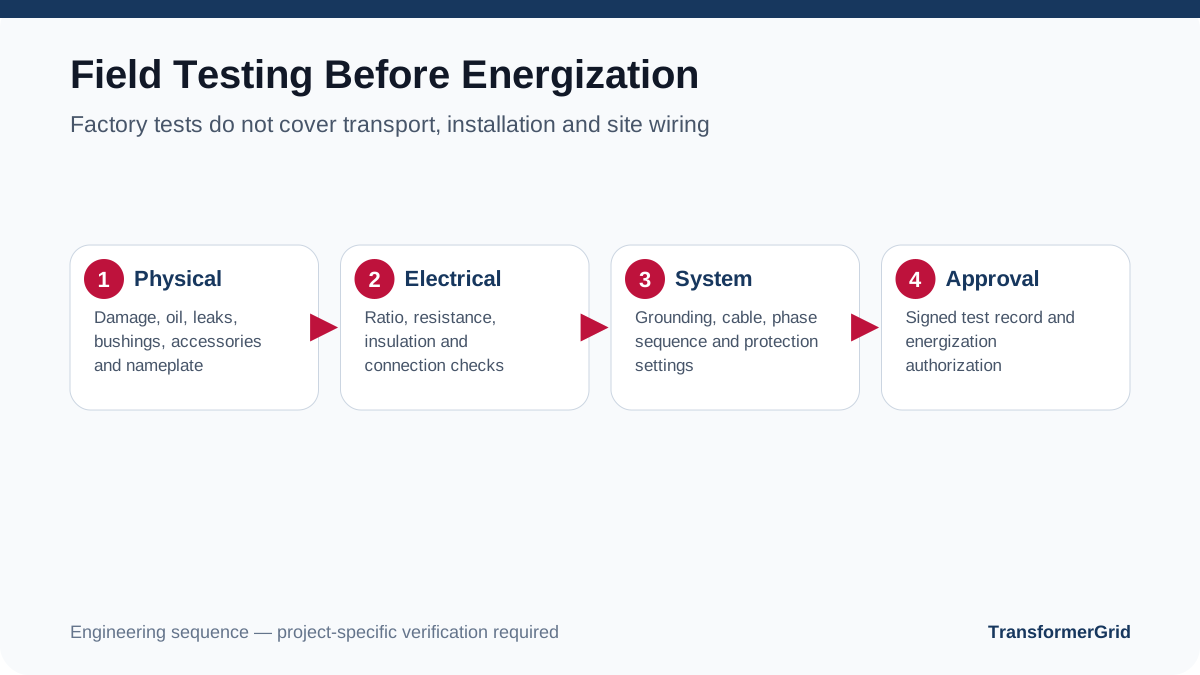
After installation, inspect mechanical securing, oil level and leaks, bushings and terminals, grounding, accessories, phase arrangement, nameplate and transport damage.
Field Testing and Energization
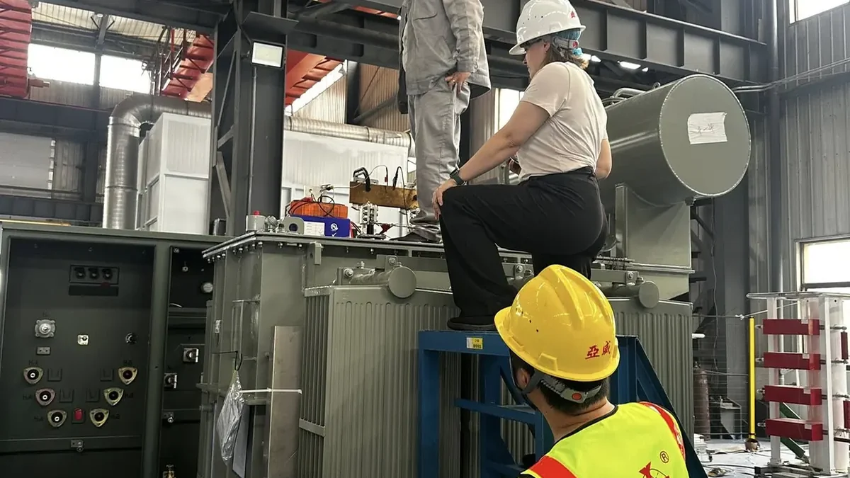
The project determines the field-test program. It may include insulation, ratio, winding resistance, connection and phase relation, grounding, oil and accessories, protection circuits, cable tests and functional checks.
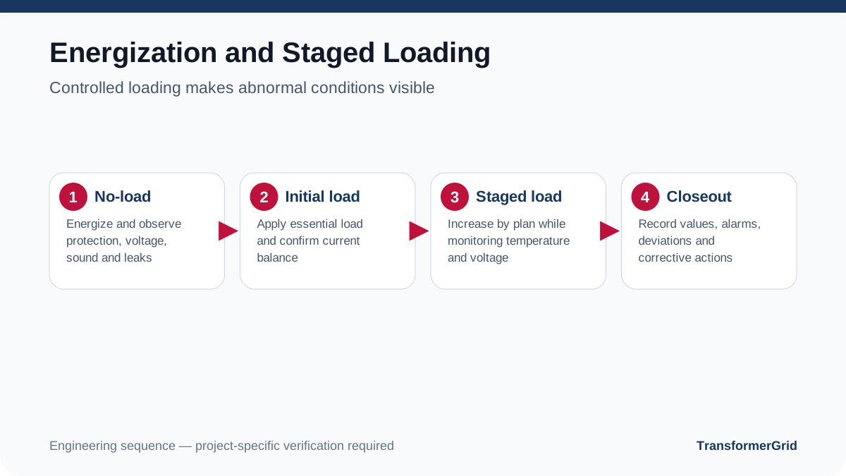
Energization should follow an approved procedure. A common controlled sequence is no-load energization; observation of sound, smell, leaks, protection status and voltage; then staged loading with recorded current, voltage, temperature and alarms.
Roles, Hold Points and Contingency Decisions
The outage plan should identify an authorized decision maker for each hold point. Typical hold points include confirming that the replacement unit and accessories are on site, approving temporary-power readiness, accepting the condition of the foundation or pole after the old unit is removed, releasing field-test results, approving protection settings and authorizing energization.
A contingency plan should also state what happens if cable damage, weak grounding, foundation misalignment, unexpected transport damage or failed field tests are discovered. The response may be to repair within the outage, extend temporary power, install a temporary transformer or return the site to a safe de-energized condition. Pre-agreed authority and communication prevent schedule pressure from overriding safety or acceptance evidence.
Handover and Early-Life Observation
Handover should include final drawings, nameplate, test reports, protection settings, energization records, changes, maintenance plan, spare parts and emergency contacts.
Early follow-up may include leakage, connection heating, loading, temperature, sound and protection alarms according to project requirements and manufacturer guidance.
Related buying guide: Read the commercial decision guide that applies this technical framework to cost, scope and RFQ review.
FAQ
Is generator capacity selected only from total connected load?
No. Critical-load selection, motor starting, power factor, grounding, transfer method and runtime also matter.
Are field checks required after factory acceptance tests?
Yes. Transport, installation, cable, grounding, protection and site wiring introduce risks that factory tests cannot cover.
Should the new transformer be loaded fully at once?
Follow the approved procedure. Staged loading often makes connection, protection and operating abnormalities easier to identify.
This Technical Library page is educational. Project design, protection settings, construction, permits and energization must be completed by the utility and appropriately qualified local parties. TransformerGrid coordinates RFQ clarification, drawings, documents, FAT and export delivery with verified manufacturing partners.